Posts

Showing posts with the label CNC

Custom Mountain Bike Suspension Yoke

Image
Custom Mountain Bike Suspension Yoke Project Goal Test CNC capabilities and quality of JLC PCB's CNC machining service The part I decided to design is a replacement suspension yoke for my YT Capra Core 2, here is the final result mounted on the bike: The Process Took off existing suspension yoke from mountain bike Re-model it in Solidworks 3D print to test fitting on bike Generate engineering drawings for tolerances and threads Upload to JLCPCB for quote - it was ~$60 USD Wait 1.5 weeks for it to arrive Results The machined yoke from JLC PCB (left), the existing yoke from factory (right) The original yoke was made from Aluminium, not sure the specific alloy so I requested 6061 as most bike manufactures use that The mass is ~50g lighter than the original yoke - due to a slightly modified design I have been riding it and so far no issues. Simulation indicated all experiences loads are within the capabilities of 6061 Al.  CAD Model

CNC Mill Axis Assembly Updates

Image
In the previous post I mentioned my concerns with the height and amount of parts needed for each axis assembly. The main problem was due to the ball screw (SFU1204) alignment bearings being tall (39 mm). This meant the guide rails and linear bearings needed to match that height in order for the table to clear (to get the full build area range).  Here is the updated design: The SFU1204 ball screw is being used, along with the BF/BK10 end housings. However, instead of MGN15H linear rails and bearings, a higher profile HGH 25 rails are being used with HGH 25CA linear bearings ( linked here is the plan ). The total height of bearing on rail is 40 mm, which gives 1 mm of clearance which should be enough (if not i can purchase precision 1-5 mm spacers ). Another change is the motor mount. This should be easier to fabricate out of a piece of aluminium with the tools at hand. The pre-made OTS components per axis are now: SFU1204 ball screw BF/BK10 housing 2x HGH 25 rails 4x HGH 25CA linear...

CNC Mill CAD Design

Image
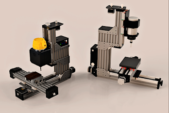
I started the CAD design for the CNC mill. I had several requirements and goals in mind that led the design process. The mill can be constructed with the tools available to me Minimal parts Re-usability of sub-assemblies Strong frame I came up with this design. The work area is 250 x 180 x 150 mm in the x-y-z directions respectively. I mostly focused on the x and y axes and need a better design for the z gantry where the spindle is attached. There are some shortcomings which will be discussed below. I started by designing the x-axis and by picking which OTS components I would need. I went with a ball screw (the SFU1204 standard) and a pair of 15 mm linear rails with MGN15H trucks. The reason why I went with a ball screw over a lead-screw is for the precision and rigidity benefits and also being able to back drive the table if needed.  The design works well however with the ball screws, the guide bearing assembly is quite large/tall which means that I have to lift the linear rails s...

First Post for a DIY CNC Machine

Image
I have been wanting to have access to a CNC machine for milling materials. There are several good options available however I think it would be interesting to design and develop one from scratch while also it being cheaper. I need to flesh out the requirements for this project however at a high level the CNC machine should be able to: Mill aluminium parts at decent speeds Have a cost of ~$1500 CAD Be compact to fit in my laundry or garage While looking online there are several good designs that hobbyists use to create their CNC mills.