Posts

AS5048A Magnetic Encoder and STM32

Image
This past week I began to write the controller firmware - mainly playing with the AS5048A angular position sensor from AMS. Here is the datasheet .  This sensor will be used to get the rotor position and then compute the resulting electrical angle for the Clarke/Park transforms and also it will be used to find rotor speed for the out loop.  I will be using an STM32F446 board to run the loop as it has a high clock speed. The AS5048A sends its measurements over SPI. Below is the read package sent from the sensor: We get 14 bits of position data - aka 16384 ticks per revolution, or a resolution of 0.0219 degrees. I wrote this read() function that sends the SPI command package and reads the resulting response: uint16_t read(uint16_t registerAddress) { uint16_t command = 0x4000; // PAR=0 R/W=R uint8_t RxBuff[2]; uint8_t TxBuff[2]; command = command | registerAddress; command |= (uint16_t) (spiCalcEvenParity(command) << 0xF); TxBuff[0] = command >> 8; TxBuf...

First Post on a AC Servo Drive Project + Current Loop Simulation

Image
Introduction Over the past year I have been working on a motor driver for an AC hobby motor (total time about a month due to school and work) - I decided to document my past developments and continue the project as I am less busy. I looked back and refined what I wanted out of this motor drive. Requirements Have precise control of position, speed, and torque of an AC motor No torque ripple in output Controller should be suitable for a wide range of PMSM motors Goals Small PCB footprint (~50 mm squared) Develop software to tune controller profiles and gains Constraints Design drive for permanent magnet synchronous machines (PMSM) with surface mounted magnets (non-salient motor) Use field oriented control (FOC) to modulate phase currents End board should be <$100 CAD To clarify, these PMSMs are hobby grade motors used for drones/UAVs, however the goal is to make it work with any sinusoidally wound brushless motor.

Revised CNC Mill Design

Image
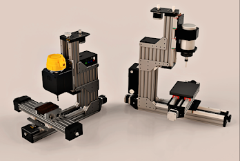
In the last post I fixed some of the clearance and parts issues for the x-axis assembly for the CNC mill. I since applied these same changes to all axes and dialed in most of the components. Here is a image of the full system:  Version 2 of the CNC mill design. The entire assembly weighs 48 kg which is on the lighter side. To fix this I plan on casting epoxy granite around the y-axis base to add both mass and damping properties.  The work area is: X travel: 240 mm Y travel: 180 mm Z travel: 110 mm Parts Each of the axes use SFU1204 ball screws, the only difference being the length: 500 mm on x, 400 mm on y, and 300 mm on z. Similar to this, all axes use HGR25 linear rails (a pair) and 4 HGH25-CA linear bearings (2 per rail). Again the only difference is the lengths: 500 mm on x, 400 mm on y, and 300 mm on z. For the spindle I plan on using a 1.5 kW 110 V air cooled spindle and a VFD ( found here ). I modelled the dimensions in Solidworks (as seen above). The motors are just NE...

CNC Mill Axis Assembly Updates

Image
In the previous post I mentioned my concerns with the height and amount of parts needed for each axis assembly. The main problem was due to the ball screw (SFU1204) alignment bearings being tall (39 mm). This meant the guide rails and linear bearings needed to match that height in order for the table to clear (to get the full build area range).  Here is the updated design: The SFU1204 ball screw is being used, along with the BF/BK10 end housings. However, instead of MGN15H linear rails and bearings, a higher profile HGH 25 rails are being used with HGH 25CA linear bearings ( linked here is the plan ). The total height of bearing on rail is 40 mm, which gives 1 mm of clearance which should be enough (if not i can purchase precision 1-5 mm spacers ). Another change is the motor mount. This should be easier to fabricate out of a piece of aluminium with the tools at hand. The pre-made OTS components per axis are now: SFU1204 ball screw BF/BK10 housing 2x HGH 25 rails 4x HGH 25CA linear...

CNC Mill CAD Design

Image
I started the CAD design for the CNC mill. I had several requirements and goals in mind that led the design process. The mill can be constructed with the tools available to me Minimal parts Re-usability of sub-assemblies Strong frame I came up with this design. The work area is 250 x 180 x 150 mm in the x-y-z directions respectively. I mostly focused on the x and y axes and need a better design for the z gantry where the spindle is attached. There are some shortcomings which will be discussed below. I started by designing the x-axis and by picking which OTS components I would need. I went with a ball screw (the SFU1204 standard) and a pair of 15 mm linear rails with MGN15H trucks. The reason why I went with a ball screw over a lead-screw is for the precision and rigidity benefits and also being able to back drive the table if needed.  The design works well however with the ball screws, the guide bearing assembly is quite large/tall which means that I have to lift the linear rails s...

First Post for a DIY CNC Machine

Image
I have been wanting to have access to a CNC machine for milling materials. There are several good options available however I think it would be interesting to design and develop one from scratch while also it being cheaper. I need to flesh out the requirements for this project however at a high level the CNC machine should be able to: Mill aluminium parts at decent speeds Have a cost of ~$1500 CAD Be compact to fit in my laundry or garage While looking online there are several good designs that hobbyists use to create their CNC mills.