Posts

Showing posts from December, 2021

Completion of the VFD - PCB and Demo

Image
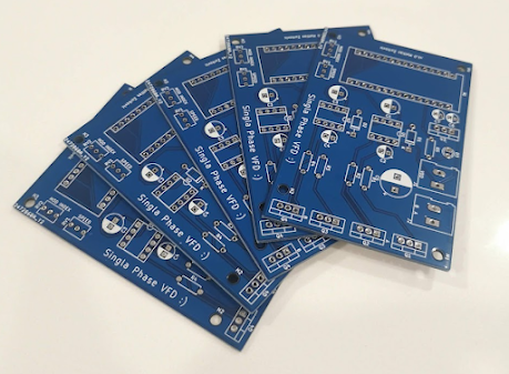
  This past week the PCB order was delivered from JLCPCB. The traces came out great: The VFD PCBs I used THT components since I was not familiar with JLC's SMT service and I had plenty of the required components stocked. From the image below, the modulation index (MOD INDEX) potentiometer is not being used since I decided manual amplitude adjustment is not required. The assembled PCB with component The VFD uses open loop volts/frequency (V/Hz) control. In a nutshell, V/Hz control works to keep the ratio between applied voltage and frequency constant such that the flux in the rotor is constant. This means that across different speeds a constant torque is applied: $$\phi = \frac{V}{4.44 f K T}$$ For this motor the V/Hz ratio is $120 V / 60 Hz = 2$. This means that is the frequency is increased by 1 Hz, the voltage is increased by 2 V.  Induction motor speed vs voltage characteristic From the graph above, in the linear region, this V/Hz ratio can be seen as the slope of the line. For

VFD Updates - More Prototyping and PCB Design

Image
Several things have been done since the initial prototype: the prototype has been further tested, the motor has been validated, and the PCB has been designed and sent to the FAB. Here is an image of the rendered board: The PCB render Prototype Validation The prototype has been changed - specifically gate and pull-down resistors were added. A big change is that the inverter generates a 12 V peak to peak signal which is then boosted up to 120 V RMS by a transformer and powers the motor. This was done instead of having a 120 V sine wave be generated as an isolated power supply would be needed for the logic components, however the current being drawn at the inverter stage is significantly higher. Here are some key waveforms generated by the inverter. The switching voltage between inverter legs A and B The filtered output voltage The firmware is running a 100% modulation index, thus showing that the output wave has peaks of $\pm V_{dc}$ or $\pm 12 V$. The frequency can also be modulated to